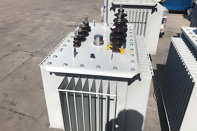
Oil-Immersed Transformer Voltage Parameter Table: Key Selection Guide
Choosing the correct voltage parameters for oil-immersed transformers is essential for ensuring long-term stability, energy efficiency, and safety. As a core component of the power grid, the transformer's voltage selection directly impacts system performance and equipment lifespan. This guide outlines critical voltage characteristics and selection logic based on real-world applications.
1. Voltage Level Matching: Grid and Load Side
Grid-Side Voltage
The transformer’s primary voltage should match the nominal voltage of the supply network—commonly 10kV, 20kV, or 35kV. Voltage fluctuation ranges (typically ±10%) must be considered.
In rural areas or remote terminals, voltage may drop significantly. In such scenarios, a transformer with a broader tapping range is necessary to compensate.
Load-Side Voltage
The low-voltage side—such as 0.4kV or 6.3kV—must align with the rated voltage of the electrical load. For sensitive or precision equipment, it's critical to reserve a margin for voltage regulation to prevent instability or performance issues.
2. Tap Changer Selection: Voltage Fluctuation Control
A tap changer adjusts the transformer's turns ratio to stabilize output during input voltage variations.
For applications with large voltage fluctuations (such as photovoltaic grid connections), select a tap range of ±10%. For stable industrial power environments, a ±5% tap range is typically sufficient.
On-load tap changers are preferred for systems that require dynamic voltage adjustment without shutdown.
3. Insulation Design: Withstand Environmental and Electrical Stress
The transformer must handle both power frequency voltage and lightning impulse voltage beyond system operating levels.
High-Altitude Considerations
At elevations above sea level, air insulation performance drops—approximately 10% per 1000 meters. In these cases, reinforce insulation or adjust ratings accordingly.
Dirty and Humid Environments
In polluted or moist conditions, increase creepage distance, use higher insulation grades, or select sealed designs to maintain insulation reliability.
4. Short-Circuit Impedance: Balancing Efficiency and Protection
| Impedance Type | Range | Advantages | Disadvantages | Application |
|---|---|---|---|---|
| High Impedance | 6–10% | Reduces fault current, protects downstream devices | Higher operational losses | Urban substations, industrial networks |
| Low Impedance | 4–6% | Better efficiency, improved voltage regulation | Higher short-circuit current | Rural or small-scale systems |
5. Typical Transformer Selection Process
Step 1: Confirm the existing grid voltage and evaluate potential upgrades over the next 5–10 years.
Step 2: Analyze load characteristics, including startup impact and harmonic content.
Step 3: Calculate short-circuit capacity and ensure alignment with system protection devices.
Step 4: Adjust design for environmental factors such as altitude, pollution level, and ambient temperature.
6. Pitfalls to Avoid During Selection
Do not select transformers based solely on nominal voltage. Always evaluate the actual voltage fluctuation range to ensure performance under all conditions.
Overdesign—such as excessive insulation or an overly wide tap range—can increase capital cost without delivering proportional operational benefit. However, underdesigning may lead to system instability and expensive retrofits later.
Voltage parameter selection for oil-immersed transformers is a systematic engineering task that involves coordination between grid-side voltage, load-side requirements, tap changer range, insulation strength, short-circuit impedance, and environmental factors.
Only by applying a comprehensive and scenario-based approach can users select transformers that offer reliable, cost-effective, and long-term performance. For complex configurations or high-voltage systems, always consult a professional transformer engineer to ensure optimal selection.
oil immersed transformer lifespan
oil immersed transformer maintenance
transformer lifecycle
transformer insulation aging
dry type transformer temperature monitoring
- more+releated article
- 2026-05-11How Long Does an Oil-Immersed Transformer Last
- 2026-05-08Modern Power System Dry-Type Transformer Insta
- 2026-05-07Oil-Immersed Transformer Overheating: Causes,
- 2026-05-07Dry-Type Transformers for Data Centers: 2026 R
- 2026-04-30Air-Core Reactor vs Iron-Core Reactor: How to
- 2026-04-29Compact Enclosed Transformer for Smart Grid: T
- 2026-04-2812-Pulse and 24-Pulse Phase-Shifting Transform
- 2026-04-27Oil-Immersed Transformers for Industrial Plant
- 2026-04-25Why Dry-Type Transformers Are Preferred for Ho
- 2026-04-24Enclosed Transformer Outdoor Solutions: IP Pro
- ELECTRICAL INSULATION BOARD MATERIALS
- ELECTRICAL INSULATION MATERIALS
- POWER TRANSFORMER
- ENAMELED WIRE
- SWITCHGEAR


transformer insulation aging
transformer lifecycle
oil immersed transformer lifespan
oil immersed transformer maintenance
dry type transformer installation
dry type transformer temperature monitoring
dry type transformer maintenance
dry type transformer sizing
transformer cooling system failure
transformer overheating causes
oil immersed transformer overheating
transformer oil temperature
harmonic mitigation
dry type transformer
K factor transformer
data center transformer
Cast resin transformer
insulation oil degradation
DGA analysis transformer
transformer fault analysis
oil immersed transformer failure
smart grid transformer
compact enclosed transformer
integrated distribution transformer
compact transformer substation