Working Principle of a Transformer
What is transformer?
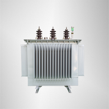
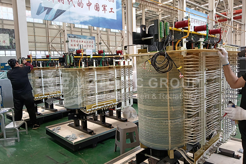
A transformer is a device that uses the principle of electromagnetic induction to change the AC voltage. The main components are the primary winding, the secondary winding and the iron core (magnetic core). In a generator, an electrical potential can be induced in the coil, whether the coil moves through a magnetic field or the magnetic field moves through a stationary coil. In both cases, the value of the magnetic flux is unchanged, but the amount of magnetic flux that intersects with the coil changes, which is the principle of mutual induction. A transformer is a device that uses electromagnetic mutual induction to transform voltage, current and impedance.
Electromagnetic induction
When the AC supply is given to the primary winding with a voltage of V1, an alternating flux ϕ sets up in the core of the transformer, which links with the secondary winding and as a result of it, an emf is induced in it called Mutually Induced emf. The direction of this induced emf is opposite to the applied voltage V1, this is because of the Lenz’s law shown in the figure below:
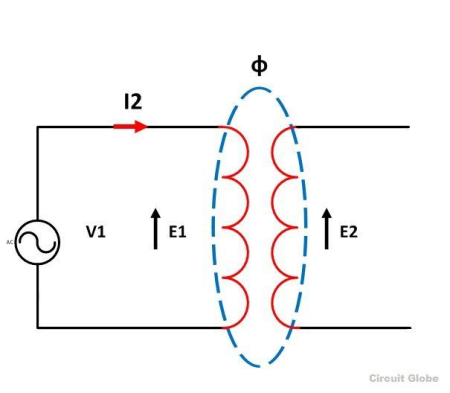
Physically, there is no electrical connection between the two windings, but they are magnetically connected. Therefore, the electrical power is transferred from the primary circuit to the secondary circuit through mutual inductance.
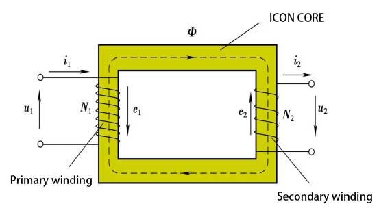
The induced emf in the primary and secondary windings depends upon the rate of change of flux linkage that is (N dϕ/dt).
dϕ/dt is the change of flux and is same for both the primary and secondary windings. The induced emf E1 in the primary winding is proportional to the number of turns N1 of the primary windings (E1 ∞ N1). Similarly induced emf in the secondary winding is proportional to the number of turns on the secondary side. (E2 ∞ N2).
change in voltage
When the AC voltage U1 is applied to the primary side of the transformer, the current flowing through the primary winding is I1, and the current will generate an alternating magnetic flux in the iron core, so that the primary winding and the secondary winding are electromagnetically connected. According to the principle of electromagnetic induction, alternating When the magnetic flux passes through these two windings, an electromotive force will be induced, and its magnitude is proportional to the number of winding turns and the maximum value of the main magnetic flux. The side with more winding turns has a higher voltage, and the side with fewer winding turns has a lower voltage. When the secondary side of the transformer is open, that is, when the transformer is no-load, the voltage at the primary and secondary terminals is proportional to the number of turns of the primary and secondary windings, that is, U1/U2=N1/N2, but the primary and secondary frequencies are kept the same, so that the voltage Variety.
Turn Ratio
It is defined as the ratio of primary to secondary turns.
n=N1/N2
If n>1 the transformer is called Step down transformer
If n<1 the transformer is called Step-up transformer
Transformer on DC supply
As discussed above, the transformer works on AC supply, and it cannot work not DC supply. If the rated DC voltage is applied across the primary winding, a constant magnitude flux will set up in the core of the transformer and hence there will not be any self-induced emf generation, as for the linkage of flux with the secondary winding there must be an alternating flux required and not a constant flux.According to Ohm’s Law
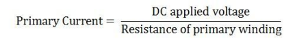
The resistance of the primary winding is very low, and the primary current is high. So this current is much higher than the rated full load primary winding current. Hence, as a result, the amount of heat produced will be greater and therefore, eddy current loss (I2R) loss will be more.
Because of this, the insulations of the primary windings will get burnt, and the transformer will get damaged.
Transformation Ratio
The transformation ratio is defined as the ratio of the secondary voltage to the primary voltage. It is denoted by K.
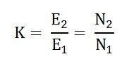
As (E2 ∞ N2 and E1 ∞ N1)
This is all about the working of the transformer.
Article Reference Sources:
https://circuitglobe.com/working-principle-of-a-transformer.html#TurnRatio
oil immersed transformer lifespan
oil immersed transformer maintenance
transformer lifecycle
transformer insulation aging
dry type transformer temperature monitoring
- more+releated article
- 2026-05-11How Long Does an Oil-Immersed Transformer Last
- 2026-05-08Modern Power System Dry-Type Transformer Insta
- 2026-05-07Oil-Immersed Transformer Overheating: Causes,
- 2026-05-07Dry-Type Transformers for Data Centers: 2026 R
- 2026-04-30Air-Core Reactor vs Iron-Core Reactor: How to
- 2026-04-29Compact Enclosed Transformer for Smart Grid: T
- 2026-04-2812-Pulse and 24-Pulse Phase-Shifting Transform
- 2026-04-27Oil-Immersed Transformers for Industrial Plant
- 2026-04-25Why Dry-Type Transformers Are Preferred for Ho
- 2026-04-24Enclosed Transformer Outdoor Solutions: IP Pro
- ELECTRICAL INSULATION BOARD MATERIALS
- ELECTRICAL INSULATION MATERIALS
- POWER TRANSFORMER
- ENAMELED WIRE
- SWITCHGEAR


transformer insulation aging
transformer lifecycle
oil immersed transformer lifespan
oil immersed transformer maintenance
dry type transformer installation
dry type transformer temperature monitoring
dry type transformer maintenance
dry type transformer sizing
transformer cooling system failure
transformer overheating causes
oil immersed transformer overheating
transformer oil temperature
harmonic mitigation
dry type transformer
K factor transformer
data center transformer
Cast resin transformer
insulation oil degradation
DGA analysis transformer
transformer fault analysis
oil immersed transformer failure
smart grid transformer
compact enclosed transformer
integrated distribution transformer
compact transformer substation