
How to Size a 3500 kVA Transformer: Load & Demand Factor
A 3500 kVA transformer is a common choice for factories, data centers, mines, hospitals and large commercial buildings. It sits in the range where a wrong size is expensive. Too small, and you face overheating, voltage drop and early failure. Too large, and you pay more for the unit, the cable and the switchgear, while running at poor efficiency.
This guide shows how to size a 3500 kVA transformer correctly. You will learn how to work from connected load to demand load, apply power factor and growth margin, and then verify current, impedance and fault level.
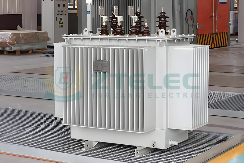
What a 3500 kVA Transformer Really Means
The rating of 3500 kVA is apparent power. It is the product of voltage and current, not the real power in kilowatts. The real power you can draw depends on the power factor of your load.
At a power factor of 0.9, a 3500 kVA transformer can deliver about 3,150 kW. At 0.8, it delivers only 2,800 kW. This is why power factor matters as much as the nameplate.
Step 1: List the Connected Load
Start by adding up every load the transformer will feed. Include motors, drives, lighting, HVAC, process heating, welding equipment, UPS systems and any spare circuits.
Record each load in kW or kVA. If the data is in horsepower, convert it first. One horsepower equals roughly 0.746 kW. For motors, use the nameplate input power, not just shaft output.
The total is your connected load. It is a theoretical maximum. It almost never occurs in real life, because not every machine runs at full output at the same time.
Step 2: Apply the Demand Factor
The demand factor links connected load to actual peak demand. It is the ratio of maximum demand to total connected load.
A demand factor of 0.75 means the real peak is 75 percent of everything installed. Typical values vary by facility type. Heavy continuous industry may reach 0.8 to 0.95. General manufacturing often sits between 0.6 and 0.8. Offices and commercial buildings are frequently lower.
Use measured data whenever you have it. A year of utility bills or a power-quality log gives a far better number than a rule of thumb. If you are designing a new plant, use values from similar sites and apply a safety allowance.
Step 3: Consider Diversity and Load Factor
Two related terms often get confused with demand factor, so it helps to separate them.
Diversity Factor
Diversity factor describes the fact that different loads peak at different times. It is the sum of individual peak demands divided by the combined system peak. It is always 1 or greater. When several feeders share one transformer, diversity can reduce the size you need.
Load Factor
Load factor is average load divided by peak load over a period. It tells you how steady the load is. A high load factor means the transformer runs near its peak for long hours, which creates more heat. A low load factor gives the winding time to cool, and may allow a slightly tighter size.
Demand factor sets the peak. Load factor describes the shape of the load. Good sizing looks at both.
Step 4: Convert kW to kVA with Power Factor
Once you have the maximum demand in kW, divide by the power factor to find the kVA the transformer must supply.
If your plant has a poor power factor, the transformer must be larger for the same real power. Power factor correction capacitors can lower the kVA demand and sometimes let you choose a smaller unit. Always confirm that the capacitors will not create resonance with harmonic loads.
Step 5: Add a Growth Margin
Transformers last 25 to 40 years. Your load will probably grow during that time. Most engineers add 15 to 25 percent for future expansion.
Do not stack margins without thought. If your demand factor already includes a safety allowance, a large extra margin may leave the transformer lightly loaded. A transformer that runs below 30 percent of its rating for most of its life wastes energy through no-load losses.
A common design target is a normal operating load between 60 and 80 percent of the nameplate rating.
Worked Example: Sizing a 3500 kVA Transformer
Here is a simple calculation for a manufacturing plant.
| Item | Value |
|---|---|
| Total connected load | 3,600 kW |
| Demand factor | 0.75 |
| Maximum demand | 2,700 kW |
| Power factor | 0.90 |
| Demand in kVA | 3,000 kVA |
| Growth margin | 15% |
| Required size | 3,450 kVA |
| Nearest standard rating | 3,500 kVA |
The result of 3,450 kVA rounds up to the standard 3500 kVA rating. The transformer would run at about 86 percent of nameplate at the future peak, and about 75 percent at today’s peak. That is a healthy range for most industrial duty.
Step 6: Check the Full Load Current
After choosing the kVA, calculate the rated current on each side. This drives cable size, breaker rating and busbar selection.
The table below shows the full load current for a 3500 kVA three-phase transformer at common voltages.
| Line Voltage | Full Load Current (approx.) |
|---|---|
| 33 kV | 61 A |
| 13.8 kV | 146 A |
| 11 kV | 184 A |
| 690 V | 2,929 A |
| 480 V | 4,210 A |
| 415 V | 4,869 A |
| 400 V | 5,052 A |
On the low-voltage side, currents above 4,000 A are demanding. They call for large busway, parallel cables and high-rated breakers. For this reason, many designers prefer a medium-voltage secondary such as 690 V or higher, or they split the load across two smaller transformers.
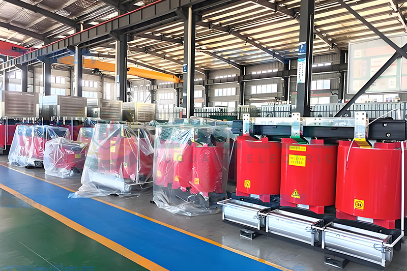
Step 7: Select the Impedance and Check Fault Level
Percent impedance controls both voltage regulation and short-circuit current. A typical 3500 kVA transformer has an impedance between 6 and 8 percent.
The maximum fault current on the secondary can be estimated from the full load current divided by the per-unit impedance.
For a 480 V unit with 6 percent impedance, the secondary fault current is near 70 kA, assuming an infinite source. Your switchgear and breakers must be rated to withstand and interrupt that level. A higher impedance lowers the fault current but increases voltage drop. You must balance the two.
Step 8: Account for Motor Starting
Large motors draw five to seven times their rated current during direct-on-line starting. This causes a temporary voltage dip. If the dip is too deep, contactors drop out and sensitive equipment trips.
Check the largest motor against the transformer size. A common rule is to keep the starting kVA of the biggest motor below about 15 to 20 percent of the transformer rating, unless you use soft starters or variable frequency drives. Drives reduce inrush, but they add harmonics.
Step 9: Allow for Harmonics
Variable frequency drives, rectifiers, LED lighting and UPS systems create harmonic currents. These raise eddy-current losses in the windings and core, which causes extra heating.
If non-linear loads make up a large share of the demand, consider a K-rated transformer or apply a derating factor. In heavy harmonic environments, a 3500 kVA transformer may need to be treated as if it were smaller in effective capacity.
Step 10: Adjust for Ambient Temperature and Altitude
Standard ratings assume a maximum ambient temperature of 40 °C and an altitude below 1,000 meters. Outside these limits, the cooling is less effective and the unit must be derated or specially designed.
For high-altitude sites, the thin air reduces heat transfer and also lowers insulation strength. For hot climates, a higher temperature-class insulation system or added cooling fans can help. Always tell the manufacturer about site conditions at the enquiry stage.
Dry Type or Oil-Immersed?
Both types are available at 3500 kVA. Dry type and cast resin units suit indoor installations, buildings and places where fire safety is critical. Oil-immersed units usually offer lower cost, better overload tolerance and lower losses, and they suit outdoor substations.
The choice does not change the sizing method, but it affects cooling class, overload capacity and installation requirements.
Consider Efficiency and Losses
A 3500 kVA transformer can run for decades, so losses matter. No-load loss is constant whenever the unit is energized. Load loss rises with the square of the current.
Ask for loss figures in the quotation and compare the total cost of ownership, not only the purchase price. A more efficient unit often repays its higher price within a few years, especially under continuous duty.
Common Sizing Mistakes to Avoid
Many sizing errors repeat across projects. Watch for these.
First, using connected load as if it were demand. This leads to oversizing. Second, ignoring power factor and sizing in kW instead of kVA. Third, forgetting growth, then overloading within five years. Fourth, stacking several safety margins, which results in a lightly loaded unit. Fifth, overlooking harmonics, fault level or motor starting.
Quick Sizing Checklist
Before you place the order, confirm each point: the connected load is listed, the demand factor is based on data, the power factor is realistic, growth is included once, the full load current matches your switchgear, the impedance suits the fault level, motor starting is acceptable, harmonics are addressed, and site conditions are given to the supplier.
Sizing a 3500 kVA transformer is a structured process. Begin with the connected load, apply a realistic demand factor, convert to kVA using the power factor, and add a measured growth margin. Then verify current, impedance, fault level, motor starting and harmonics.
A well-sized transformer runs cool, stays efficient and serves your facility for decades. If you are unsure about your load profile, share your data with a qualified transformer manufacturer. They can review your calculation and recommend the right rating, voltage, vector group and cooling class for your project.
how to size a transformer
transformer sizing
demand factor
3500 kVA transformer
load factor
- more+releated article
- 2026-10-19How to Size a 3500 kVA Transformer: Load &
- 2026-10-163500 kVA Transformer Nameplate Guide: Ratings,
- 2026-10-1523 kV Transformer Secondary Voltage: 400 V vs
- 2026-10-143500 kVA 23 kV Oil-Immersed Transformer: Speci
- 2026-10-13Pad-Mounted Transformer: Applications in Under
- 2026-10-12Meet ZTELEC at Powerexpo Almaty 2026
- 2026-10-10S11 vs. S13 vs. S20 Oil Immersed Transformers:
- 2026-10-09KYN28-12 Switchgear: Technical Specifications
- 2026-10-08Transformer Price List 2026: Cost per kVA in C
- 2026-09-30Chinese Transformer Factory Tour: Behind the S
- ELECTRICAL INSULATION BOARD MATERIALS
- ELECTRICAL INSULATION MATERIALS
- POWER TRANSFORMER
- ENAMELED WIRE
- SWITCHGEAR


FR-4 Copper-Free Laminate | High-Performance Insulation Material

FR-4 Copper Clad Laminate Manufacturer & Supplier
3500 kVA transformer
load factor
demand factor
transformer sizing
how to size a transformer
transformer nameplate guide
vector group
3500 kVA transformer nameplate
400 V transformer
23 kV transformer secondary voltage
400 V vs 416 V
416 V transformer
3500 kVA oil immersed transformer specifications
23 kV oil-immersed transformer
pad mount transformer applications
underground distribution transformer
pad-mounted transformer
Powerexpo Almaty 2026
Almaty power exhibition
ZTELEC Yuguang Electric
transformer supplier Kazakhstan
oil immersed transformer comparison
S13 transformer
S11 vs S13 vs S20
S11 transformer