European Type Compact Substation Wiring Diagram Explained: HV & LV Connections
European type compact substations are widely used in modern power distribution systems. They are commonly installed in cities, industrial parks, renewable energy projects, and commercial facilities.
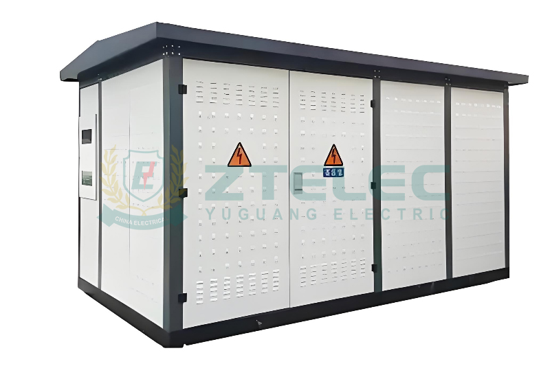
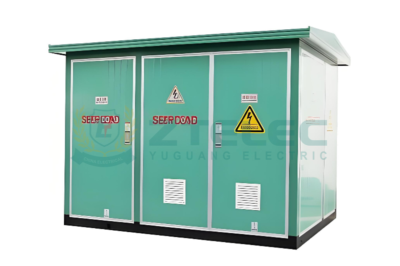
These substations combine high-voltage switchgear, transformers, and low-voltage distribution equipment in one enclosure. This compact design improves safety, saves space, and simplifies installation.
To understand how such a system works, the wiring diagram is essential. It shows how power enters the substation, how it passes through each component, and how it is delivered to end users.
Purpose of a Compact Substation Wiring Diagram
A wiring diagram explains the electrical logic of the substation. It shows how each device is connected and how protection functions are coordinated.
For engineers, the diagram supports design review and commissioning. For operators and maintenance staff, it is the main reference for safe operation and fault handling.
Main Structure Shown in the Wiring Diagram
A European type compact substation is normally divided into three compartments. Each compartment has a clear function and independent protection.
The high-voltage compartment contains medium-voltage switchgear. The transformer compartment houses the power transformer. The low-voltage compartment includes the distribution switchboard.
The wiring diagram follows this structure. It clearly separates HV, transformer, and LV circuits to improve safety and readability.
High-Voltage Side Wiring Explained
The high-voltage side connects the substation to the medium-voltage grid. Typical operating voltages include 10kV, 11kV, 20kV, and 33kV.
Most European type compact substations use a ring main unit on the HV side. The wiring diagram usually shows two incoming feeders connected through load break switches.
This ring network design improves supply reliability. If one feeder fails, the other feeder can continue supplying power.
The transformer feeder is protected by a fuse-switch combination or a circuit breaker. The wiring diagram shows how this feeder connects to the transformer high-voltage terminals.
Grounding is clearly indicated in the diagram. Cable screens, metal enclosures, and surge arresters are connected to the earthing system to protect people and equipment.
Transformer Connections Between HV and LV
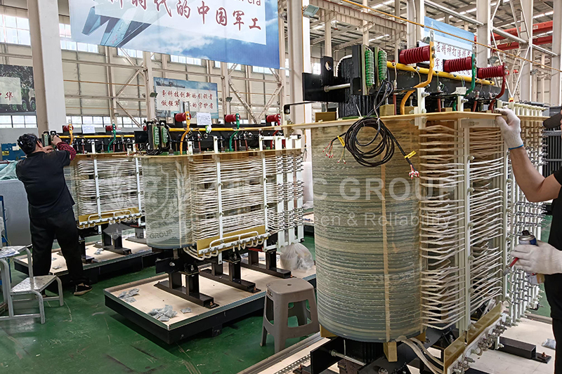
The transformer links the high-voltage and low-voltage systems. It reduces the medium voltage to a usable low-voltage level.
The wiring diagram identifies the transformer type and vector group, such as Dyn11. This information defines phase displacement and neutral arrangement.
On the HV side, the transformer is connected using screened cables or separable connectors. On the LV side, the secondary terminals connect directly to the main busbars.
Correct phase sequence and neutral grounding are clearly shown. This ensures stable operation and compatibility with downstream loads.
Low-Voltage Side Wiring Explained
The low-voltage system normally operates at 400V or 415V. It supplies power to multiple outgoing feeders.
The wiring diagram shows the main incoming circuit breaker connected to the transformer secondary. This breaker provides overload and short-circuit protection.
Outgoing feeders are connected through circuit breakers mounted on the LV switchboard. Each feeder is clearly labeled in the wiring diagram.
Neutral and protective earth conductors are also shown. Proper grounding is essential for electrical safety and IEC compliance.
Control, Measurement, and Auxiliary Circuits
In addition to power circuits, the wiring diagram includes control and measurement wiring. These circuits support monitoring and protection functions.
Current transformers and voltage transformers are connected to meters and protection relays. The diagram shows secondary wiring routes and grounding points.
Auxiliary circuits supply power to control devices, heaters, lighting, and ventilation systems. These circuits are protected separately from main power circuits.
IEC Standards Reflected in the Diagram
European type compact substations are mainly designed according to IEC standards. The wiring diagram reflects these requirements.
Common references include IEC 62271 for high-voltage equipment, IEC 61439 for low-voltage assemblies, and IEC 60076 for transformers.
Compliance with these standards ensures correct insulation levels, protection coordination, and testing procedures.
Value During Installation and Maintenance
During installation, the wiring diagram helps verify cable termination, grounding, and phase sequence. Correct wiring reduces commissioning risks.
During operation, the diagram supports fault location and safe isolation. Clear wiring documentation helps reduce downtime and maintenance costs.
The European type compact substation wiring diagram clearly explains how HV and LV systems are connected through the transformer.
Understanding this diagram is essential for engineers, operators, and maintenance teams working with compact substations.
A well-structured wiring diagram, designed according to IEC standards, ensures safe operation, reliable power supply, and long-term performance.
oil immersed transformer lifespan
oil immersed transformer maintenance
transformer lifecycle
transformer insulation aging
dry type transformer temperature monitoring
- more+releated article
- 2026-05-11How Long Does an Oil-Immersed Transformer Last
- 2026-05-08Modern Power System Dry-Type Transformer Insta
- 2026-05-07Oil-Immersed Transformer Overheating: Causes,
- 2026-05-07Dry-Type Transformers for Data Centers: 2026 R
- 2026-04-30Air-Core Reactor vs Iron-Core Reactor: How to
- 2026-04-29Compact Enclosed Transformer for Smart Grid: T
- 2026-04-2812-Pulse and 24-Pulse Phase-Shifting Transform
- 2026-04-27Oil-Immersed Transformers for Industrial Plant
- 2026-04-25Why Dry-Type Transformers Are Preferred for Ho
- 2026-04-24Enclosed Transformer Outdoor Solutions: IP Pro
- ELECTRICAL INSULATION BOARD MATERIALS
- ELECTRICAL INSULATION MATERIALS
- POWER TRANSFORMER
- ENAMELED WIRE
- SWITCHGEAR


transformer insulation aging
transformer lifecycle
oil immersed transformer lifespan
oil immersed transformer maintenance
dry type transformer installation
dry type transformer temperature monitoring
dry type transformer maintenance
dry type transformer sizing
transformer cooling system failure
transformer overheating causes
oil immersed transformer overheating
transformer oil temperature
harmonic mitigation
dry type transformer
K factor transformer
data center transformer
Cast resin transformer
insulation oil degradation
DGA analysis transformer
transformer fault analysis
oil immersed transformer failure
smart grid transformer
compact enclosed transformer
integrated distribution transformer
compact transformer substation