
Inverter Duty Solar Transformers – Key Specs for Utility-Scale Projects
In utility-scale solar power plants, photovoltaic modules and inverters receive most of the attention, but the transformer installed between the inverter output and the medium-voltage collection network is equally critical. The inverter duty solar transformer is responsible for safely increasing low-voltage AC power from solar inverters to medium voltage while ensuring stable energy transmission throughout the entire PV plant.
Unlike conventional distribution transformers, inverter duty transformers are specially designed to withstand harmonic currents, rapid switching transients, thermal cycling, and fluctuating loads caused by modern power electronics. Selecting an unsuitable transformer can result in overheating, insulation degradation, increased losses, unexpected failures, and reduced solar plant availability.
This guide explains the key technical specifications, design considerations, and international standards that engineers, EPC contractors, and renewable energy developers should evaluate when selecting inverter duty transformers for utility-scale solar projects.
What Is an Inverter Duty Solar Transformer?
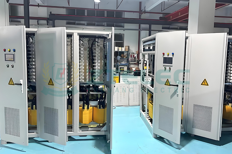
An inverter duty solar transformer is a specialized step-up transformer installed directly after a solar inverter or inverter station. Its primary function is to increase the inverter's low-voltage AC output, typically 480V, 600V, or similar voltage levels, to a medium-voltage level such as 13.8kV, 23kV, 33kV, or 34.5kV for connection to the solar plant's collector system.
In a typical utility-scale photovoltaic project, each inverter station is connected to a dedicated inverter duty transformer. Multiple transformers then feed the medium-voltage collection network before electricity reaches the main substation and grid connection point.
The key difference between an inverter duty transformer and a standard transformer is the ability to handle the electrical characteristics created by inverter-based generation, including harmonic distortion, high-frequency switching, voltage fluctuations, and repetitive voltage stress from IGBT or SiC semiconductor switching technology.
Why Standard Distribution Transformers Are Not Suitable for Solar Applications
Traditional distribution transformers are designed for relatively stable sinusoidal loads operating at standard power frequency. Solar inverter outputs are fundamentally different because they are generated through power electronic switching technology.
During operation, solar inverters introduce several challenges:
Harmonic currents: PWM switching generates harmonic components that increase stray losses, eddy current losses, and winding heating inside the transformer.
High-frequency switching stress: Rapid voltage changes create additional insulation stress on transformer windings.
Variable loading conditions: Solar generation changes continuously due to sunlight intensity, weather conditions, and daily operating cycles.
Thermal cycling: Transformers experience repeated heating during daytime operation and cooling during nighttime shutdown, accelerating insulation aging.
For projects designed to operate for 25 to 35 years, conventional transformers may experience reduced lifetime performance under these conditions. Therefore, utility-scale solar plants typically require transformers specifically engineered for inverter duty operation according to industry guidelines such as IEEE C57.110.
Key Specifications for Inverter Duty Solar Transformers
1. Transformer Capacity and kVA Rating
The transformer kVA rating must match the inverter output capacity while considering future expansion, environmental conditions, and operating margins. Solar transformer selection should not rely only on the inverter nameplate rating but should also consider the actual power generation profile throughout the year.
Many utility-scale projects choose slightly oversized transformers to accommodate future inverter upgrades, higher photovoltaic module output, bifacial solar panel performance improvements, and unexpected increases in generation capacity.
2. Voltage Ratio and Tap Adjustment
Solar inverter transformers typically step up low-voltage inverter output to medium-voltage collection levels. Common voltage configurations include 0.48kV/13.8kV, 0.6kV/23kV, and 0.69kV/34.5kV.
Most inverter duty transformers are equipped with no-load tap changers (NLTC) to adjust voltage ratios and compensate for voltage drops caused by long medium-voltage feeder systems. Proper tap range selection helps maintain stable voltage at the grid interconnection point.
3. Harmonic Capability and K-Factor Rating
Harmonic performance is one of the most important differences between solar transformers and standard transformers. Since inverter output contains harmonic currents, transformer design must consider additional heating caused by increased eddy current losses.
Engineers typically evaluate transformer capability using harmonic loss calculations or K-factor ratings based on IEEE C57.110 recommendations. A properly designed inverter duty transformer prevents excessive temperature rise and ensures long-term reliability under non-linear loads.
4. Insulation System and Temperature Rise
Utility-scale solar transformers often use enhanced insulation systems designed for frequent thermal cycling. High-temperature insulation materials such as Nomex or equivalent insulation systems are commonly selected to improve aging resistance.
The transformer design should consider not only continuous operating temperature but also repeated daily heating and cooling cycles that occur naturally in photovoltaic applications.
5. Cooling System Selection
Cooling design depends on transformer capacity, installation environment, and project requirements.
Common cooling methods include:
ONAN (Oil Natural Air Natural): Used for smaller and medium-capacity oil-filled solar transformers.
ONAN/ONAF: Combines natural cooling and forced air cooling for larger transformer ratings where additional capacity is required.
Dry-type cooling systems: Used in specific applications where fire safety, indoor installation, or environmental restrictions require non-liquid insulation technology.
6. Transformer Impedance
Transformer impedance directly affects fault current levels, voltage regulation, and coordination between multiple inverter stations connected to the same medium-voltage network.
During system design, impedance values should be coordinated with inverter characteristics and protection settings to achieve reliable operation while maintaining acceptable voltage regulation.
7. Basic Impulse Level (BIL) Rating
Solar farms are commonly installed in open areas where lightning exposure and switching surges can affect equipment reliability. The transformer BIL rating should match the system voltage class and local environmental conditions.
Proper coordination between transformer insulation levels and surge protection devices helps prevent insulation failures caused by transient overvoltage events.
8. Environmental Protection and Enclosure Design
Utility-scale solar plants are often located in harsh environments including deserts, coastal regions, and areas with large temperature variations.
Transformer specifications should include appropriate corrosion protection, weather-resistant coatings, sealing systems, and enclosure protection ratings such as IP or NEMA classifications. Cooling radiators and ventilation designs should also consider high ambient temperatures.
9. Monitoring and Protection Accessories
Modern inverter duty solar transformers are increasingly equipped with intelligent monitoring systems to support predictive maintenance and integration with plant SCADA systems.
Typical accessories include temperature sensors, alarm and trip contacts, pressure relief devices, sudden pressure relays, dissolved gas analysis monitoring interfaces, and protection current transformers.
These monitoring functions allow operators to identify abnormal conditions early, reduce maintenance costs, and improve overall solar plant availability.
10. Efficiency and Total Cost of Ownership
Transformer efficiency evaluation should include both purchase cost and lifetime operating losses. Since solar transformers frequently operate at partial load, no-load losses and core losses can significantly influence long-term energy consumption.
Using total cost of ownership analysis helps project developers select transformers that provide the best economic performance throughout the expected 25 to 35-year service life of the solar plant.
International Standards for Solar Inverter Transformers
Inverter duty solar transformers are generally designed and tested according to internationally recognized transformer standards, including:
IEEE C57.12.00 and IEEE C57.12.90: General requirements and testing methods for liquid-immersed transformers.
IEEE C57.110: Recommended practice for transformer capability under non-sinusoidal load currents.
IEC 60076 Series: International standards covering transformer design, testing, and performance requirements.
UL and Utility Interconnection Requirements: Additional requirements related to protection coordination, grounding, and grid connection compliance.
EPC contractors and utility companies often require transformer manufacturers to provide routine test reports, type tests, temperature rise tests, and impulse test certificates before equipment approval.
How to Select the Right Inverter Duty Transformer for Solar Projects
Selecting the correct transformer requires coordination between the solar inverter manufacturer, EPC contractor, and transformer supplier.
Key factors that should be confirmed during the engineering stage include inverter harmonic characteristics, medium-voltage collection system voltage, environmental conditions, transformer cooling requirements, protection scheme design, SCADA integration needs, and lifetime operating cost evaluation.
Early technical coordination helps avoid compatibility problems, reduces commissioning risks, and ensures the transformer can operate reliably throughout the entire lifecycle of the photovoltaic project.
Why Inverter Duty Transformers Are Essential for Utility-Scale Solar Plants
Inverter duty solar transformers are not standard distribution transformers with minor modifications. They are specially engineered power equipment designed to handle the unique electrical and environmental challenges of modern photovoltaic generation systems.
By considering harmonic loading capability, thermal performance, insulation design, voltage requirements, cooling systems, protection accessories, and international standards, developers and EPC contractors can significantly improve solar plant reliability and reduce long-term operating costs.
For utility-scale PV projects, selecting an experienced transformer manufacturer with proven solar application experience is one of the most important steps toward achieving stable grid integration and dependable 25-year-plus operation.
Solar Power Transformer
Utility Scale Solar Transformer
inverter duty solar transformer
PV Step Up Transformer
PV Inverter Duty Transformer
- more+releated article
- 2026-07-18Inverter Duty Solar Transformers – Key Specs
- 2026-07-18315 KVA Cast Resin Dry Type Transformer for Ho
- 2026-07-162000 kVA Oil-Immersed Transformer: A Reliable
- 2026-07-152026 Prefabricated Substation FAQ: 20 Essentia
- 2026-07-142026 Oil-Immersed Transformer Efficiency Stand
- 2026-07-13China Transformer After-Sales Support: A Compl
- 2026-07-1133kV Compact Substations for Industrial Parks:
- 2026-07-10China Oil-Immersed Transformer Manufacturers:
- 2026-07-09Prefabricated Substations for Africa & Eme
- 2026-07-08How to Order Dry-Type Transformer Samples from
- ELECTRICAL INSULATION BOARD MATERIALS
- ELECTRICAL INSULATION MATERIALS
- POWER TRANSFORMER
- ENAMELED WIRE
- SWITCHGEAR



Utility Scale Solar Transformer
Solar Power Transformer
inverter duty solar transformer
PV Inverter Duty Transformer
PV Step Up Transformer
315 kVA dry type transformer
315 kVA cast resin dry-type transformer
school transformer
hospital transformer
distribution transformer
2000 kVA oil filled transformer
2000 kVA oil immersed transformer
box type substation
prefabricated transformer substation
Prefabricated Substation FAQ
Compact Substation Guide
DOE transformer standards
Ecodesign transformer
EU Ecodesign
oil immersed transformer efficiency standards
transformer warranty
transformer spare parts
transformer after-sales service
China transformer procurement
industrial park substation