
3500 kVA Transformer Load Factor: Losses, Heat & Life
A 3500 kVA transformer is a major asset. It often feeds a factory, a mine, a data hall or a solar plant, and it is expected to run for decades. How hard you load it decides three things: how much energy it wastes, how hot it runs, and how long its insulation lasts.
This guide explains load factor in plain terms. It shows how losses, heat and service life connect, and it gives practical loading targets you can use when sizing or reviewing a 3500 kVA unit.
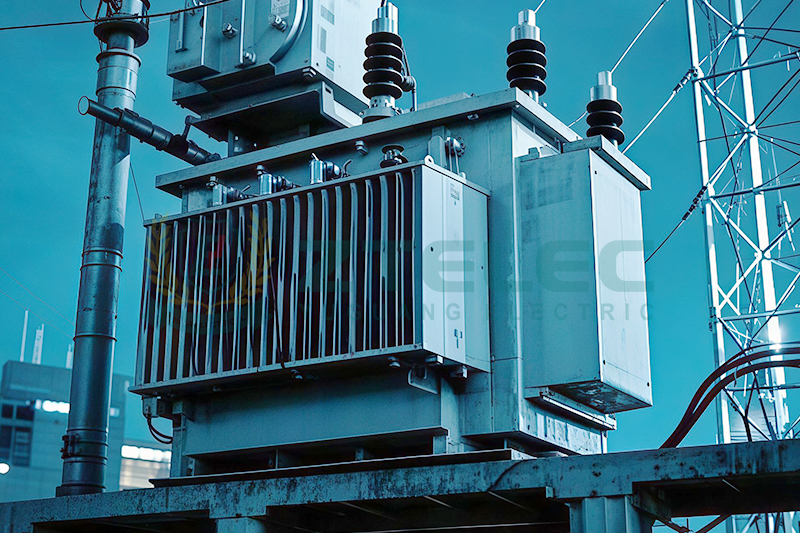
What Is Transformer Load Factor?
Load factor is the average load divided by the peak load over a given period. A plant that peaks at 2,800 kVA but averages 1,400 kVA has a load factor of 0.5.
It describes how steady your demand is. A high load factor means the transformer works close to its peak most of the time. A low one means short peaks and long quiet periods.
Load Factor vs Loading Ratio
These two terms are often mixed up. Load factor compares average demand with peak demand. The loading ratio, sometimes called per-unit load or utilisation, compares actual load with the nameplate rating.
For a 3500 kVA transformer carrying 2,100 kVA, the loading ratio is 0.6, or 60 percent. Both numbers matter. The load factor tells you the shape of the demand curve, and the loading ratio tells you how close the transformer sits to its limits.
Why the Distinction Matters
Losses depend on the square of the current, so the peaks do more damage than the averages suggest. Two sites with the same average load can age a transformer at very different rates if one has a flat profile and the other has sharp spikes.
Where a 3500 kVA Transformer Loses Energy
Every transformer has two kinds of loss. They behave very differently as load changes.
No-Load Loss (Core Loss)
No-load loss comes from magnetising the core. It is present whenever the transformer is energised, even with nothing connected. It stays almost constant from zero load to full load.
Core steel quality drives this number. Amorphous alloy cores can cut no-load loss sharply compared with standard silicon steel.
Load Loss (Copper Loss)
Load loss comes from current flowing through the windings, plus stray losses in the tank and structure. It rises with the square of the load. Double the current and the copper loss quadruples.
This is why a heavily loaded transformer gets hot quickly, and why a lightly loaded one wastes little in its windings.
The Basic Loss Formula
Total loss at any loading can be written as: P = P0 + (K² × Pk). Here P0 is the no-load loss, Pk is the rated load loss, and K is the per-unit load. This simple equation explains almost everything that follows.
Worked Example: Losses at Different Loads
The figures below are illustrative. A typical 3500 kVA oil-immersed unit might have a no-load loss of about 4.5 kW and a rated load loss of about 30 kW. Your actual values come from the manufacturer's test report.
| Loading | Load (kVA) | No-load loss (kW) | Load loss (kW) | Total loss (kW) |
|---|---|---|---|---|
| 25% | 875 | 4.5 | 1.9 | 6.4 |
| 40% | 1,400 | 4.5 | 4.8 | 9.3 |
| 60% | 2,100 | 4.5 | 10.8 | 15.3 |
| 80% | 2,800 | 4.5 | 19.2 | 23.7 |
| 100% | 3,500 | 4.5 | 30.0 | 34.5 |
Notice how total loss grows about fivefold between 25 percent and 100 percent loading, while output grows fourfold. Efficiency stays high throughout, but the cost of running hot builds up over thousands of hours.
The Efficiency Sweet Spot
A transformer reaches its maximum efficiency when load loss equals no-load loss. The loading at which this happens is the square root of the ratio of no-load loss to rated load loss.
With the example numbers, that is the square root of 4.5 divided by 30, or roughly 0.39. The peak efficiency sits near 39 percent loading.
Why You Should Not Chase the Peak
Designing for peak efficiency alone would mean buying a larger transformer than you need. A bigger unit costs more up front and carries a higher no-load loss all year.
Most distribution transformers are designed so their efficiency curve is flat across the 40 to 70 percent range. That is the zone where most real installations operate, and it is a sensible target for a 3500 kVA unit.
Energy Cost Over the Year
Because the core is always energised, no-load loss accrues for all 8,760 hours of the year. At 4.5 kW that is about 39,400 kWh annually. Load loss only accrues while current flows, so a plant running two shifts pays less copper loss than one running around the clock.
When comparing quotes, capitalise both loss figures over the expected life. A cheaper transformer with higher losses is often the more expensive choice over 20 years.
How Load Factor Drives Heat
Losses turn into heat. That heat must leave through the tank surface, radiators or cooling air. The balance between heat generated and heat removed sets the operating temperature.
Temperature Rise Components
Three temperatures matter. The top-oil or winding temperature rise over ambient, the average winding rise, and the hot-spot temperature, which is the hottest point inside the winding. The hot-spot is the one that governs insulation ageing.
Standard oil-immersed units are typically designed for a 65 K average winding rise and a 55 K top-oil rise at rated load. Dry type units depend on their insulation class. Class F allows roughly 100 K winding rise, and class H allows about 125 K.
Ambient Temperature Counts
Rise is measured above ambient. A transformer in a 40 degree Celsius desert yard starts from a much higher baseline than one in a cool climate. The same load factor produces a hotter hot-spot in a hot environment.
Poor ventilation, blocked radiators and direct sun all add to this. At high altitude, thinner air also reduces cooling, so derating may be needed.
Thermal Time Constants
Heat does not appear instantly. Oil has a large thermal mass, so a 3500 kVA oil-immersed transformer may take several hours to reach a steady temperature after a load change. Windings respond faster, in minutes.
This is why short peaks are often tolerable. A brief spike above rating may not push the hot-spot to a damaging level, while a sustained overload will.
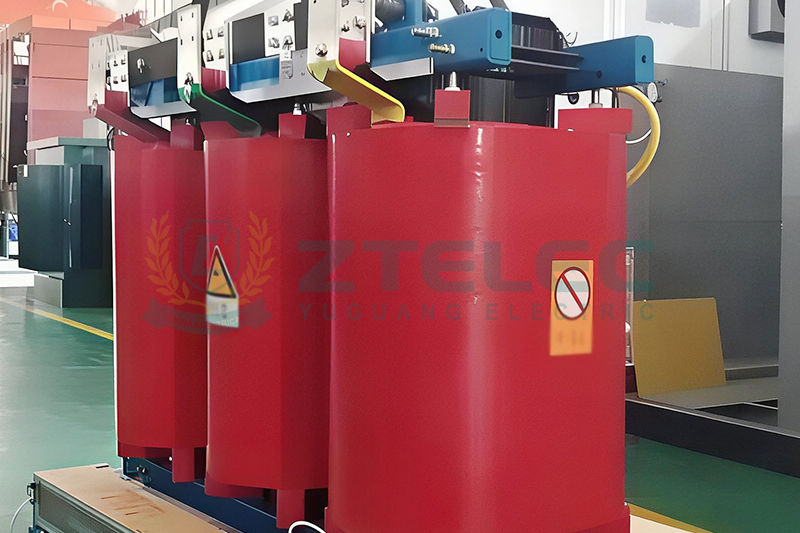
Heat and Insulation Life
The paper insulation around the windings is the real life-limiting component. Heat breaks down the cellulose chains, making the paper brittle and weak. Once it loses its mechanical strength, the winding can fail during a short circuit.
The Six-Degree Rule of Thumb
Ageing follows a chemical reaction curve. As a rough guide, every 6 to 8 degrees Celsius rise in hot-spot temperature roughly doubles the ageing rate. Run 12 degrees hotter than design for long, and you may cut remaining life to a quarter.
Standards such as IEC 60076-7 and IEEE C57.91 give formulas for relative ageing. They use a reference hot-spot of around 98 to 110 degrees Celsius, depending on insulation type and ambient assumptions.
What Normal Life Looks Like
A well-loaded oil-immersed transformer is commonly expected to last 25 to 40 years. Many run longer. Dry type units usually have a similar design life when kept clean, dry and within their temperature class.
These numbers assume loading that keeps the hot-spot near its reference value. Chronic overloading is the fastest way to shorten them.
Moisture, Oxygen and Oil Quality
Heat is not the only enemy. Water in the paper speeds up ageing, and oxygen makes it worse. A sealed or nitrogen-cushioned conservator and regular oil testing slow the process.
Dissolved gas analysis can reveal overheating long before a fault. It is one of the best tools for judging how a transformer has actually aged.
Practical Loading Targets for 3500 kVA
There is no single perfect number, but good practice points to a clear range. Aim for a peak loading of 70 to 80 percent of nameplate, with an average loading around 40 to 60 percent.
That range keeps the hot-spot below the design limit, leaves headroom for growth, and keeps efficiency close to its maximum. It also gives the transformer spare capacity to absorb short emergency overloads.
When Load Factor Is Low
If the average load sits below 25 percent, the transformer is probably oversized. You pay for core loss all year while the copper does little work. Consider a smaller unit, or two smaller units that can be switched in as demand rises.
When Load Factor Is High
If the transformer runs near 90 percent or above for long periods, heat and ageing become the main risk. Check the hot-spot, improve cooling, or plan a parallel unit. Do not rely on emergency overload rules for daily operation.
Planning for Growth
Sizing for today's load plus 20 to 25 percent growth is common. It avoids both immediate overloading and years of wasted core loss. If large expansion is expected, a modular approach may be cheaper than one very large transformer.
Harmonics, Overloads and Hidden Heat
Nameplate kVA assumes a clean sinusoidal current. Variable frequency drives, rectifiers and data centre power supplies inject harmonics that raise eddy-current and stray losses in the windings and tank.
A 3500 kVA transformer feeding heavy non-linear loads can run hotter than its kVA loading suggests. In those cases, specify a K-factor rating or a harmonic-rated design, and ask for losses to be calculated at the actual harmonic spectrum.
Short-Term Overloads
Standards allow temporary loading above nameplate if the hot-spot stays within limits. This is useful for emergencies and seasonal peaks. Each overload event consumes some insulation life, so it should be the exception and not the plan.
Dry Type vs Oil-Immersed at 3500 kVA
Both types follow the same loss and heat principles, but they respond differently. Oil-immersed units have more thermal inertia and generally tolerate short overloads better. Their cooling is passive through oil and radiators.
Dry type cast resin units suit indoor sites where fire safety matters. They rely on air cooling, so room ventilation and fan reliability become part of the load factor discussion. Their temperature class sets a hard limit, and sustained overload can degrade the resin quickly.
How to Improve Your Load Factor and Extend Life
You can shape the load profile as well as choose the equipment. Spreading demand across shifts, using power factor correction and avoiding simultaneous start-up of large motors all flatten the peaks and reduce stress.
Install temperature monitoring with winding temperature indicators and alarms. Keep radiators clean, check oil levels, and test oil on a regular schedule. Small habits like these add years of service.
What to Ask Your Supplier
Request certified no-load and load loss figures, the temperature rise test report, the insulation class or oil type, and the overload capability curve. Ask whether the losses meet your efficiency standard, and how they change under your expected loading.
Frequently Asked Questions
What is a good load factor for a 3500 kVA transformer?
An average loading of 40 to 60 percent, with peaks no higher than 70 to 80 percent, is a practical target. It balances efficiency, temperature and service life.
Does a low load factor harm the transformer?
Not mechanically, but it is wasteful. Core loss continues around the clock while little useful power is delivered, so efficiency falls and the cost per kWh delivered rises.
How much does overloading shorten transformer life?
It depends on the hot-spot. A few degrees above design can be tolerated for a short time. Sustained operation 12 degrees or more above the reference can cut insulation life dramatically.
Can a 3500 kVA transformer run at 100 percent load?
Yes, within its rating and ambient conditions it is designed to. But continuous full load leaves no margin, so most engineers avoid it for routine operation.
Load factor links three things that every buyer cares about: running cost, operating temperature and service life. Core loss is constant, copper loss rises with the square of the load, and heat from both decides how fast the insulation ages.
For a 3500 kVA transformer, a moderate average loading with controlled peaks gives the best balance. Size it with growth in mind, verify the loss and temperature data with test reports, and monitor it in service. Done well, the transformer will deliver efficient power for decades.
If you are specifying a 3500 kVA oil-immersed or dry type transformer and want loss-evaluated quotations matched to your load profile, contact our engineering team with your demand data and site conditions.
load loss
no-load loss
transformer losses
3500 kVA transformer
transformer load factor
- more+releated article
- 2026-11-023500 kVA Transformer Load Factor: Losses, Heat
- 2026-10-30Copper vs Aluminium Windings: 3500 kVA Losses
- 2026-10-293500 kVA Oil-Immersed Transformer TCO: 20-Year
- 2026-10-28Transformer Cost per kVA: How to Benchmark a 3
- 2026-10-273500 kVA Oil-Immersed Transformer: Altitude De
- 2026-10-263500 kVA vs 2×1750 kVA Transformers: Cost &am
- 2026-10-2150 Hz vs 60 Hz Transformer: Design Differences
- 2026-10-20ZTELEC to Showcase Power Equipment at POWER GR
- 2026-10-19How to Size a 3500 kVA Transformer: Load &
- 2026-10-163500 kVA Transformer Nameplate Guide: Ratings,
- ELECTRICAL INSULATION BOARD MATERIALS
- ELECTRICAL INSULATION MATERIALS
- POWER TRANSFORMER
- ENAMELED WIRE
- SWITCHGEAR


FR-4 Copper-Free Laminate | High-Performance Insulation Material

FR-4 Copper Clad Laminate Manufacturer & Supplier
transformer losses
no-load loss
transformer load factor
load loss
3500 kVA transformer
copper winding transformer
copper vs aluminium windings
aluminium winding transformer
total cost of ownership transformer
3500 kVA oil-immersed transformer
20-year transformer cost
transformer TCO
3500 kVA transformer quote
oil filled transformers
ransformer cost per kVA
3500 kVA transformer price
dry cast resin transformers
high altitude transformer
transformer altitude derating
transformer derating above 1000 m
3500 kVA vs 2x1750 kVA transformer
1750 kVA transformer
two transformers vs one
23 kV transformer design
transformer frequency difference