12-Pulse and 24-Pulse Phase-Shifting Transformer Guide: Principles, Selection and Harmonic Mitigation
Variable frequency drives, UPS systems, electric arc furnaces, electrolyzers, and high-power rectifier equipment all share one common feature: they are major sources of power grid harmonics. Harmonic pollution is not just an abstract power quality issue—it directly causes motor overheating, capacitor failure, relay protection misoperation, and even complete production line shutdowns.
In high-power industrial applications, the Phase-Shifting Transformer is considered one of the most economical, stable, and reliable harmonic mitigation solutions. Among them, 12-pulse transformers and 24-pulse transformers are the two most common configurations in engineering practice.
This article systematically explains the core differences and practical value of these two solutions, covering harmonic sources, working principles, structural design, and engineering selection.
Where Do Harmonics Come From?
Before understanding phase-shifting transformers, it is necessary to first understand the source of harmonics.
In industrial power systems, rectifiers are the main harmonic sources. The most common 6-pulse rectifier (three-phase full-bridge rectifier) does not generate a pure sinusoidal current waveform on the AC side, but instead produces a distorted waveform containing large amounts of odd harmonics, mainly the 5th, 7th, 11th, 13th, 17th, and 19th harmonics.
According to Fourier analysis, the characteristic harmonic orders of a 6-pulse rectifier follow:
:contentReference[oaicite:0]{index=0}That means the 5th, 7th, 11th, 13th, and other characteristic harmonics continuously inject into the public power grid.
These harmonics cause additional heating in transformers and cables, reduce power factor, increase metering errors, and in severe cases even trigger harmonic penalty clauses from utility companies.
The core logic of a phase-shifting transformer is to create phase displacement between multiple rectifier bridges so that the harmonics generated by each bridge cancel each other on the AC side.
12-Pulse Transformer: The Most Common Entry-Level Engineering Solution
Basic Principle
A 12-pulse rectifier system consists of two parallel 6-pulse rectifier bridges. The corresponding phase-shifting transformer has two secondary windings that output three-phase voltages with a 30° phase difference.
Usually, one winding uses Y (star) connection, and the other uses △ (delta) connection. Since there is a natural 30° phase shift between Y and △ connections, this forms a standard 12-pulse rectification system.
When both rectifier bridges operate simultaneously, the 5th and 7th harmonics generated by each bridge are opposite in phase and cancel each other during superposition. Theoretically, a 12-pulse system can effectively eliminate the 5th and 7th harmonics and reduce Total Harmonic Distortion of Current (THDi) from about 30% in a 6-pulse system to below 10%.
Its lowest characteristic harmonic order becomes:
:contentReference[oaicite:1]{index=1}Typical Winding Structures
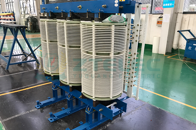
Common winding structures for 12-pulse phase-shifting transformers mainly include Y/Y-△ structure, Extended Delta structure, and Zigzag connection.
Among them, the Y/Y-△ structure is the most widely used due to its relatively simple structure and mature manufacturing process, making it suitable for most industrial rectifier systems. Extended Delta is used in applications requiring equipotential output, while Zigzag connection is mainly used for specific harmonic suppression requirements and involves higher manufacturing complexity.
Applicable Scenarios
The 12-pulse solution is especially suitable for medium and large VFD drive systems, industrial loads from 100kW to several MW, electrolysis, electroplating, DC power supply systems, and projects requiring harmonic control without extremely low THDi targets.
For retrofit projects with limited budgets where the goal is to solve major harmonic issues with minimal complexity, the 12-pulse solution is usually the most cost-effective choice.
24-Pulse Transformer: When 12 Pulses Are Not Enough
Why Upgrade to 24 Pulses?
Although the 12-pulse system can eliminate the 5th and 7th harmonics, the 11th and 13th harmonics still remain. For high-voltage grid connections, sensitive loads, or industrial environments requiring extremely high power quality, the remaining harmonics may still exceed standard limits.
In such cases, the 24-pulse phase-shifting transformer becomes the more advanced solution.
Basic Principle
A 24-pulse system uses four parallel 6-pulse rectifier bridges. The corresponding transformer has four secondary windings with a 15° phase difference between adjacent windings.
The four winding phase angles are typically 0°, 15°, 30°, and 45°. Through the superposition of four rectifier bridges, the 5th, 7th, 11th, and 13th harmonics can all be eliminated, producing an output much closer to a pure sine wave.
Its lowest characteristic harmonic order becomes:
:contentReference[oaicite:2]{index=2}This means the 23rd and 25th harmonics become the main remaining harmonics, and system THDi can typically be reduced to below 3% to 5%.
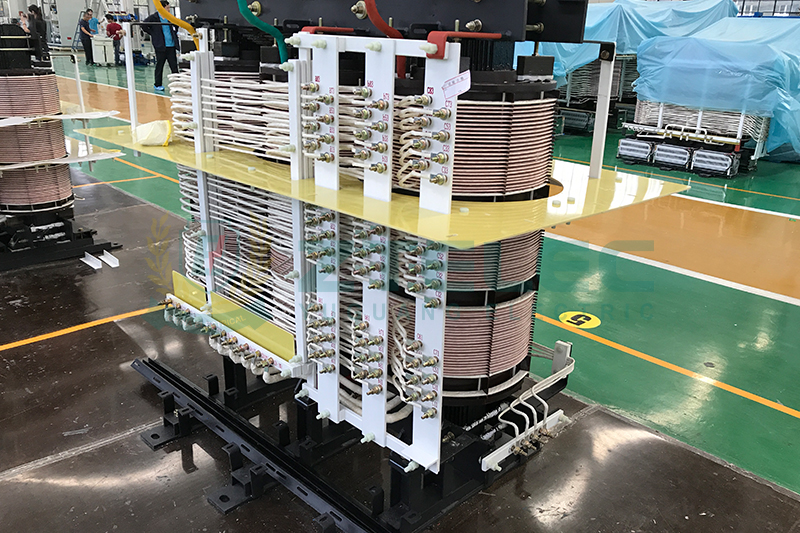
Challenges in Winding Design
Achieving an accurate 15° phase shift cannot rely on the natural 30° phase shift of Y/△ connections. It must be realized through precise winding design.
Common engineering methods include Polygon connection, Zigzag winding combinations, and auxiliary phase-shifting winding superposition. All these methods require extremely high turn ratio accuracy, impedance matching, and strict manufacturing process control.
Therefore, the structural complexity of a 24-pulse transformer is significantly higher than that of a 12-pulse solution, and its manufacturing cost is usually 1.5 to 2 times that of a 12-pulse transformer.
Applicable Scenarios
The 24-pulse solution is mainly used in large-scale aluminum electrolysis, chlor-alkali chemical plants, large electric arc furnaces, ultra-high-power DC systems, and industrial projects connected to 110kV and above high-voltage grids.
For semiconductor manufacturing, precision electronics production, and facilities with extremely high power quality requirements, the 24-pulse system provides a higher level of harmonic control.
It is also an important upgrade option for projects where an existing 12-pulse system still cannot meet harmonic standards.
12-Pulse vs 24-Pulse: How to Choose?
| Comparison Item | 12-Pulse | 24-Pulse |
|---|---|---|
| Number of Rectifier Bridges | 2 Sets | 4 Sets |
| Secondary Winding Phase Difference | 30° | 15° |
| Eliminated Harmonic Orders | 5th, 7th | 5th, 7th, 11th, 13th |
| Lowest Remaining Harmonic Order | 11th | 23rd |
| Typical THDi | 8%~12% | 3%~5% |
| Structural Complexity | Medium | High |
| Relative Cost | Baseline | About 1.5~2 Times |
| Applicable Power Range | 100kW~10MW | Above 1MW |
| Typical Applications | VFDs, Medium Rectifier Systems | Aluminum Electrolysis, Large DC Systems |
Engineering Selection Recommendations
The first step is to clarify the applicable standards. In China, GB/T 14549-1993 is commonly referenced. Large industrial users connecting to the power grid are often required to submit harmonic assessment reports. Understanding the allowable harmonic current injection limits is the foundation of transformer selection.
The second step is to calculate the existing harmonic level of the system. For operating systems, field measurements can directly evaluate whether 12-pulse meets the requirements. For new projects, harmonic simulation using professional software such as PSCAD and ETAP is strongly recommended.
The third step is to compare total life-cycle costs. Although 24-pulse systems require higher initial investment, if a 12-pulse solution cannot meet standards and requires additional Active Power Filters (APF), the total cost may not actually be lower.
The fourth step is to consider system redundancy and future expansion capability. If one rectifier bridge in a 24-pulse system fails, the system can temporarily degrade to 12-pulse operation, offering stronger continuous production capability for critical processes where shutdown is unacceptable.
Critical Details Often Overlooked in Design
DC Magnetization Problem
When multiple rectifier bridge loads are unbalanced, DC components flowing into the transformer may cause local core saturation, resulting in excitation noise and additional losses. High-quality phase-shifting transformers must be specially optimized in core design and winding balance.
Zero-Sequence Current Handling
Using △ windings can effectively block zero-sequence currents and 3rd harmonics from propagating through the system, which is one of the main reasons why delta-connected secondary windings are widely used in phase-shifting transformers.
Short-Circuit Impedance Matching
The short-circuit impedance of each secondary winding group in a multi-winding transformer must remain highly consistent. Otherwise, current distribution among rectifier bridges becomes seriously unbalanced, directly affecting harmonic cancellation performance. High-quality manufacturers usually provide complete impedance balance data in factory test reports.
Temperature Rise and Cooling Design
Phase-shifting transformers carry a higher proportion of harmonic currents, and their eddy current losses and stray losses are significantly greater than those of ordinary distribution transformers. It is generally recommended to reserve 15% to 20% capacity margin during rating design to ensure long-term stable operation.
The 12-pulse phase-shifting transformer is the most cost-effective solution for industrial harmonic mitigation, capable of meeting harmonic control requirements for most industrial applications with relatively low system complexity.
The 24-pulse solution is suitable for ultra-high-power projects, strict power quality standards, and critical applications requiring high reliability, using higher initial investment in exchange for cleaner power quality and stronger system redundancy.
There is no absolute superiority between the two solutions. The key is to make a scientific judgment based on actual load characteristics, grid connection conditions, harmonic standards, and total life-cycle costs.
For specific projects, detailed harmonic simulation analysis should always be prioritized. Data-driven decisions are far more reliable than experience-based judgment and are better aligned with the long-term operation requirements of modern industrial power systems.
oil immersed transformer lifespan
oil immersed transformer maintenance
transformer lifecycle
transformer insulation aging
dry type transformer temperature monitoring
- more+releated article
- 2026-05-11How Long Does an Oil-Immersed Transformer Last
- 2026-05-08Modern Power System Dry-Type Transformer Insta
- 2026-05-07Oil-Immersed Transformer Overheating: Causes,
- 2026-05-07Dry-Type Transformers for Data Centers: 2026 R
- 2026-04-30Air-Core Reactor vs Iron-Core Reactor: How to
- 2026-04-29Compact Enclosed Transformer for Smart Grid: T
- 2026-04-2812-Pulse and 24-Pulse Phase-Shifting Transform
- 2026-04-27Oil-Immersed Transformers for Industrial Plant
- 2026-04-25Why Dry-Type Transformers Are Preferred for Ho
- 2026-04-24Enclosed Transformer Outdoor Solutions: IP Pro
- ELECTRICAL INSULATION BOARD MATERIALS
- ELECTRICAL INSULATION MATERIALS
- POWER TRANSFORMER
- ENAMELED WIRE
- SWITCHGEAR


transformer insulation aging
transformer lifecycle
oil immersed transformer lifespan
oil immersed transformer maintenance
dry type transformer installation
dry type transformer temperature monitoring
dry type transformer maintenance
dry type transformer sizing
transformer cooling system failure
transformer overheating causes
oil immersed transformer overheating
transformer oil temperature
harmonic mitigation
dry type transformer
K factor transformer
data center transformer
Cast resin transformer
insulation oil degradation
DGA analysis transformer
transformer fault analysis
oil immersed transformer failure
smart grid transformer
compact enclosed transformer
integrated distribution transformer
compact transformer substation