
33KV GIS Switchgear Installation & Maintenance Best Practices for Long-Term Reliability
As utilities, industrial facilities, renewable energy plants, and urban substations continue to demand higher reliability within limited installation space, 33KV GIS switchgear has become one of the most preferred medium-voltage switching solutions. Compared with conventional Air-Insulated Switchgear (AIS), Gas-Insulated Switchgear (GIS) delivers a significantly smaller footprint, superior environmental protection, and lower maintenance requirements while maintaining exceptional operational reliability.
However, even the most advanced GIS system depends on correct installation and a well-planned maintenance strategy to achieve its expected 30–40-year service life. This guide explains the essential installation procedures, commissioning requirements, preventive maintenance practices, and common mistakes to avoid when operating 33KV GIS switchgear.
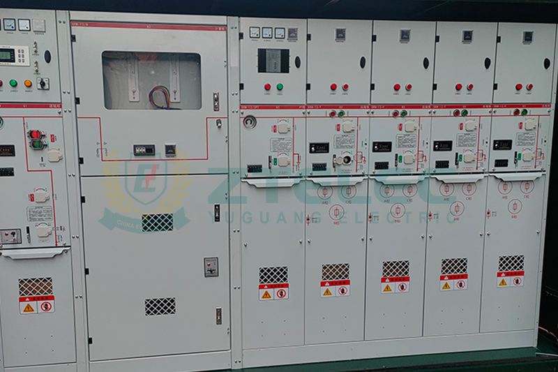
What Is 33KV GIS Switchgear?
33KV GIS switchgear is a fully enclosed metal-clad switchgear system that uses SF6 gas—or increasingly environmentally friendly alternative insulating gases—as the insulation and arc-quenching medium. All energized components, including circuit breakers, disconnectors, earthing switches, busbars, current transformers, and voltage transformers, are housed inside sealed gas compartments.
This enclosed design offers numerous operational advantages over traditional AIS systems, including improved dielectric performance, excellent resistance to dust, moisture, salt pollution, and industrial contaminants, while reducing installation space by as much as 70%.
Because of these advantages, 33KV GIS switchgear is widely deployed in:
Urban distribution substations where installation space is limited.
Industrial manufacturing plants requiring high operational reliability.
Wind farms and utility-scale solar power plants.
Data centers and mission-critical facilities.
Railway and metro electrification systems.
Mining, petrochemical, and offshore energy applications.
Why Proper Installation Is Critical
GIS equipment is manufactured with extremely tight tolerances and operates under sealed, pressurized gas conditions. Improper installation can compromise insulation performance, gas tightness, and mechanical reliability, resulting in costly outages or equipment damage.
Common installation errors include improper flange sealing, contamination inside gas compartments, incorrect bolt torque, inadequate moisture control, and poor alignment of interconnected bays. Many of these issues remain hidden until the switchgear is energized, making careful installation essential.
Site Preparation Requirements
Maintain a Clean Installation Environment
Dust, metallic particles, fibers, and other contaminants significantly reduce insulation performance inside GIS compartments. Installation areas should remain clean throughout the assembly process, with unnecessary construction work completed beforehand.
Control Humidity
Moisture is one of the leading causes of GIS insulation failure. High humidity during installation allows water vapor to enter gas compartments, reducing dielectric strength and accelerating insulation aging. Dehumidifiers should be used whenever environmental humidity exceeds manufacturer recommendations.
Ensure Foundation Accuracy
The GIS foundation must be level and dimensionally accurate to prevent mechanical stress on enclosure joints and operating mechanisms. Uneven installation may lead to gas leakage or interlocking problems during operation.
Allow Future Maintenance Access
Sufficient clearance should be reserved for cable terminations, maintenance activities, ventilation, and possible future extension of switchgear panels.
Transportation and Equipment Handling
Most 33KV GIS switchgear is delivered as factory-tested modules filled with nitrogen or insulating gas. Proper transportation and lifting procedures are essential for preserving factory quality.
Always lift equipment using designated lifting points provided by the manufacturer. Excessive tilting should be avoided because it may affect internal support structures.
Upon arrival, installation personnel should inspect:
Shipping damage.
Gas pressure indicators.
Protective covers and sealing caps.
Nameplate information and factory documentation.
If installation is postponed, equipment should be stored indoors in a dry environment, elevated above ground level, and protected from direct sunlight and rain.
GIS Assembly and Gas Filling Procedures
Inspect Flanges and Sealing Components
Before connecting adjacent GIS bays, every flange surface, gasket, and O-ring should be thoroughly cleaned and visually inspected. Damaged sealing components should never be reused.
Follow Manufacturer Torque Specifications
Bolts should be tightened using calibrated torque tools according to the prescribed tightening sequence. Uniform bolt loading ensures consistent sealing pressure and minimizes future gas leakage.
Vacuum Evacuation and Gas Filling
After assembly, each gas compartment is evacuated to remove air and moisture before filling with SF6 gas or an approved environmentally friendly insulating gas.
Critical parameters include:
Gas pressure.
Gas purity.
Dew point.
Moisture content.
These values should comply with manufacturer specifications before commissioning proceeds.
Gas Leak Testing
Each compartment must undergo leak testing using certified gas leak detection equipment. Proper sealing is essential for maintaining insulation performance and meeting environmental regulations governing SF6 emissions.
Electrical Commissioning Tests
Mechanical installation alone does not guarantee operational readiness. Comprehensive commissioning tests verify the integrity of the complete GIS installation before energization.
Recommended commissioning tests include:
Primary insulation resistance measurement.
Secondary circuit insulation testing.
Circuit breaker contact resistance measurement.
Mechanical operation verification.
Interlocking function testing.
Current transformer and voltage transformer verification.
Partial discharge (PD) testing.
SF6 gas quality analysis.
Only after all commissioning results satisfy project specifications should the switchgear be energized.
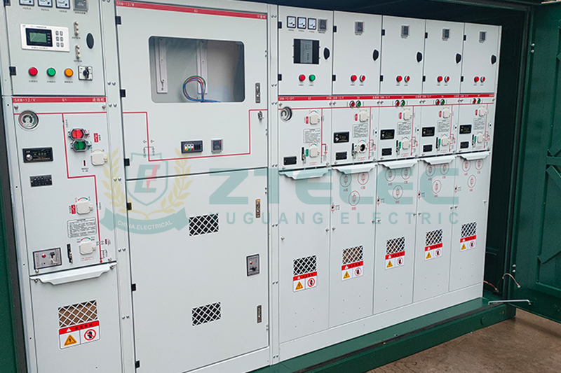
Routine Maintenance Best Practices
Although GIS requires substantially less maintenance than AIS, preventive inspection remains essential for maximizing equipment reliability and minimizing unexpected failures.
Routine Visual Inspection
Monthly or quarterly inspections should include gas pressure readings, enclosure condition, corrosion checks, alarm indicators, cable terminations, grounding connections, and control cabinet cleanliness.
Early identification of abnormal conditions greatly reduces maintenance costs.
Continuous SF6 Gas Monitoring
Gas condition directly determines insulation performance inside GIS equipment.
Maintenance personnel should routinely monitor:
Gas pressure trends.
Gas purity.
Dew point.
Moisture concentration.
Gas decomposition products such as SO₂ and HF.
Modern digital substations increasingly employ online gas monitoring systems integrated into SCADA platforms, enabling predictive maintenance instead of traditional time-based inspections.
Circuit Breaker Maintenance
The circuit breaker experiences the highest mechanical stress within the GIS assembly. Preventive maintenance should include operation counter analysis, timing tests, lubrication inspection, operating mechanism verification, and contact resistance trend analysis.
Monitoring equipment performance over time helps identify mechanical wear before failures occur.
Partial Discharge Monitoring
Partial discharge is often the earliest indication of insulation deterioration inside GIS compartments.
Regular PD monitoring using UHF sensors, acoustic sensors, or Transient Earth Voltage (TEV) technology enables maintenance teams to detect developing insulation defects long before catastrophic failures occur.
Condition-based maintenance supported by PD monitoring significantly improves asset reliability while reducing unnecessary maintenance work.
Earthing and Safety Interlock Inspection
GIS switchgear incorporates sophisticated mechanical and electrical interlocking systems designed to prevent unsafe switching operations.
Routine functional testing should verify the correct operation of:
Earthing switches.
Mechanical interlocks.
Electrical interlocks.
Protection relay logic.
Emergency operating mechanisms.
Maintaining these systems is essential for personnel safety and compliance with utility operating procedures.
Infrared Thermal Inspection
Thermal imaging provides a non-invasive method for detecting abnormal heating caused by loose electrical connections, deteriorating contacts, overloaded cable terminations, or aging auxiliary equipment.
Annual infrared inspections help identify developing issues before they affect system reliability.
Long-Term Overhaul Planning
Major GIS overhauls are generally required every 15–20 years, depending on operating conditions and switching frequency.
Typical overhaul activities include refurbishment of operating mechanisms, replacement of aging seals, gas replacement where required, inspection of busbar compartments, relay firmware upgrades, and replacement of auxiliary control components.
A planned asset management strategy minimizes downtime while extending overall equipment life.
Common Installation and Maintenance Mistakes
Several recurring mistakes significantly reduce GIS reliability. These include inadequate moisture control during installation, failure to investigate gradual gas pressure loss, neglecting partial discharge testing, poor documentation of commissioning records, and allowing unqualified personnel to handle SF6 gas.
Following manufacturer recommendations and maintaining complete maintenance records greatly improves long-term operational performance.
The Future of Eco-Friendly 33KV GIS Switchgear
As environmental regulations become increasingly stringent, many manufacturers are introducing SF6-free GIS solutions that utilize clean air, vacuum interruption technology, or fluoronitrile-based insulating gas mixtures.
These environmentally sustainable alternatives offer similar electrical performance while significantly reducing greenhouse gas emissions. Although installation procedures remain largely comparable, gas handling and monitoring requirements vary according to the insulating medium used, making manufacturer documentation especially important.
33KV GIS switchgear has become one of the most dependable medium-voltage solutions for modern substations, industrial facilities, renewable energy projects, and urban power distribution networks. Its compact design, exceptional reliability, and low maintenance requirements make it an ideal choice wherever space, safety, and operational continuity are priorities.
Nevertheless, achieving the full lifecycle value of GIS equipment requires meticulous installation, comprehensive commissioning, routine condition monitoring, and disciplined preventive maintenance. Proper site preparation, accurate gas handling, periodic partial discharge monitoring, circuit breaker maintenance, and continuous gas quality analysis all contribute to maximizing equipment reliability and extending service life.
By following manufacturer recommendations, complying with IEC 62271 standards, and adopting modern condition-based maintenance technologies, asset owners can ensure that their 33KV GIS switchgear operates safely, efficiently, and reliably for decades.
33kV gas insulated switchgear
33KV GIS Switchgear
GIS switchgear installation
dry type transformer export
GB/T 10228
- more+releated article
- 2026-07-2233KV GIS Switchgear Installation & Mainten
- 2026-07-21China Dry Type Transformer Export Standards: G
- 2026-07-201000 KVA Oil Filled Transformer for Industrial
- 2026-07-18Inverter Duty Solar Transformers – Key Specs
- 2026-07-18315 KVA Cast Resin Dry Type Transformer for Ho
- 2026-07-162000 kVA Oil-Immersed Transformer: A Reliable
- 2026-07-152026 Prefabricated Substation FAQ: 20 Essentia
- 2026-07-142026 Oil-Immersed Transformer Efficiency Stand
- 2026-07-13China Transformer After-Sales Support: A Compl
- 2026-07-1133kV Compact Substations for Industrial Parks:
- ELECTRICAL INSULATION BOARD MATERIALS
- ELECTRICAL INSULATION MATERIALS
- POWER TRANSFORMER
- ENAMELED WIRE
- SWITCHGEAR



33kV gas insulated switchgear
33KV GIS Switchgear
GIS switchgear installation
GB/T 10228
IEC 60076-11
GB/T 1094.11
China dry type transformer standards
dry type transformer export
1000 KVA oil filled transformer
1000 kVA oil immersed transformer
commercial power transformer
industrial transformer
inverter duty solar transformer
Solar Power Transformer
Utility Scale Solar Transformer
PV Inverter Duty Transformer
PV Step Up Transformer
hospital transformer
315 kVA cast resin dry-type transformer
school transformer
315 kVA dry type transformer
2000 kVA oil immersed transformer
distribution transformer
2000 kVA oil filled transformer
box type substation