
Oil Filled Transformer Series Overview: 500–2000 kVA Options
The 500–2000 kVA oil filled transformer series is widely used for medium-voltage power distribution in industrial facilities, commercial buildings, utility substations, renewable energy projects, infrastructure systems, and other high-demand applications. Available in a broad range of capacities, these transformers provide a practical combination of electrical efficiency, thermal performance, reliability, and long service life.
Oil filled transformers, also commonly referred to as oil immersed transformers, use insulating liquid for both electrical insulation and heat dissipation. Compared with dry type transformers, oil filled designs generally provide efficient heat transfer and are particularly well suited to outdoor substations and applications with demanding load profiles.
Within the 500–2000 kVA range, commonly specified ratings include 500 kVA, 630 kVA, 750 kVA, 800 kVA, 1000 kVA, 1250 kVA, 1500 kVA, 1600 kVA, and 2000 kVA. The appropriate rating depends on the site's present load, future expansion requirements, voltage level, environmental conditions, transformer impedance, efficiency requirements, and applicable electrical standards.
This guide provides a comprehensive overview of the 500–2000 kVA oil filled transformer series, covering transformer types, construction, cooling systems, applications, technical specifications, selection criteria, maintenance requirements, common problems, and emerging technologies.
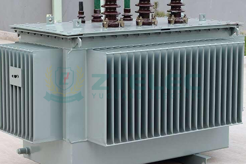
What Is an Oil Filled Transformer?
An oil filled transformer is a power transformer in which the core and windings are immersed in insulating liquid. The liquid provides two primary functions: electrical insulation and heat transfer.
During transformer operation, electrical losses generate heat in the windings and magnetic core. The insulating liquid absorbs this heat and transfers it to the transformer tank and cooling surfaces, where it is dissipated into the surrounding air.
This thermal management capability is one of the major reasons why oil immersed transformers remain widely used in utility distribution, industrial power systems, renewable energy installations, and outdoor substations.
500–2000 kVA Oil Filled Transformer Series
The 500–2000 kVA range covers many of the transformer ratings commonly required for medium-sized commercial, industrial, infrastructure, and utility distribution projects.
| Transformer Rating | Typical Applications | Common Voltage Classes |
|---|---|---|
| 500 kVA | Commercial buildings, small factories, local distribution substations | 6 kV, 10 kV, 11 kV, 20 kV, 22 kV |
| 630 kVA | Commercial facilities, industrial plants, utility distribution | 6 kV, 10 kV, 11 kV, 20 kV, 22 kV |
| 750 kVA | Industrial facilities, commercial complexes, renewable energy systems | 10 kV, 11 kV, 20 kV, 22 kV, 33 kV |
| 800 kVA | Factories, commercial facilities, infrastructure projects | 10 kV, 11 kV, 20 kV, 22 kV, 33 kV |
| 1000 kVA | Industrial plants, substations, data centers, renewable energy | 10 kV, 11 kV, 20 kV, 22 kV, 33 kV |
| 1250 kVA | Large commercial buildings, manufacturing plants, utility systems | 10 kV, 11 kV, 20 kV, 22 kV, 33 kV |
| 1500 kVA | Heavy industry, mining, manufacturing, renewable energy projects | 10 kV, 11 kV, 20 kV, 22 kV, 33 kV |
| 1600 kVA | Industrial distribution and medium-sized substations | 10 kV, 11 kV, 20 kV, 22 kV, 33 kV |
| 2000 kVA | Large factories, utility substations, data centers, infrastructure | 10 kV, 11 kV, 20 kV, 22 kV, 33 kV |
The exact voltage combinations, impedance, losses, tap range, insulation level, vector group, cooling class, enclosure design, and accessories should be confirmed according to the project specification and applicable standards.
Why Choose a 500–2000 kVA Oil Filled Transformer?
Efficient Heat Dissipation
Transformer oil provides an effective medium for transferring heat away from the windings and core. Natural oil circulation combined with natural air cooling is commonly used for many distribution transformer applications.
For transformers with higher thermal requirements, forced-air cooling can be added to increase heat dissipation capacity.
High Electrical Efficiency
Modern oil filled transformers can be designed with low no-load and load losses. High-quality electrical steel, optimized magnetic flux density, and efficient winding designs help reduce energy losses throughout the transformer's service life.
For projects with continuous operation, even relatively small improvements in transformer losses can produce significant lifecycle energy savings.
Long Service Life
A properly designed, manufactured, installed, and maintained oil filled transformer can provide decades of service. Service life depends on insulation aging, operating temperature, loading, moisture, oil condition, maintenance quality, and environmental conditions.
Cost-Effective Power Distribution
Oil filled transformers are often attractive for outdoor distribution systems because their cooling technology is well established and available across a wide range of capacities and voltage classes.
Wide Application Range
The 500–2000 kVA capacity range is suitable for many applications, from commercial buildings and manufacturing plants to utility substations, solar power projects, mining facilities, and infrastructure systems.
Applications of 500–2000 kVA Oil Filled Transformers
Utility Distribution
Utility companies use oil filled distribution transformers to reduce medium voltage to usable distribution voltage for commercial, residential, and industrial customers.
Typical installations include ground-mounted substations, distribution substations, industrial parks, and rural electrification projects.
Industrial Facilities
Factories, steel plants, mining operations, chemical plants, manufacturing facilities, and processing plants often require reliable medium-voltage transformers to supply motors, production equipment, HVAC systems, lighting, and auxiliary loads.
For industrial projects, transformer selection should consider not only total kVA demand but also motor starting currents, harmonics, load cycles, ambient temperature, and future production expansion.
Commercial Buildings
Shopping centers, office complexes, hotels, hospitals, warehouses, and large commercial buildings may use 500–1500 kVA oil filled transformers where site conditions and local electrical regulations permit.
For indoor installations, fire protection, containment, ventilation, local regulations, and the characteristics of the insulating liquid must be carefully evaluated. Dry type transformers may be preferred in some indoor applications.
Renewable Energy Projects
Solar farms, wind farms, battery energy storage systems, and other renewable energy facilities require transformers to interface electrical generation equipment with medium-voltage collection systems and utility grids.
The appropriate transformer rating depends on generation capacity, inverter configuration, ambient conditions, collection voltage, and grid connection requirements.
Mining and Heavy Industry
Mining operations and heavy industrial facilities often operate under demanding environmental and electrical conditions. Oil filled transformers can provide robust thermal performance for applications with high and continuously varying loads.
Infrastructure Projects
Railway facilities, airports, ports, water treatment plants, municipal infrastructure, and large public facilities may also use oil filled transformers as part of their medium-voltage distribution systems.
Key Construction Features of 500–2000 kVA Oil Filled Transformers
Magnetic Core
The transformer core is generally manufactured using grain-oriented electrical steel laminations. High-quality core material and optimized core design help reduce no-load losses and improve overall efficiency.
Copper or Aluminum Windings
Windings can be manufactured using copper or aluminum conductors. Copper provides high conductivity and strong mechanical properties, while aluminum can provide weight and material-cost advantages in suitable designs.
The best conductor material depends on the transformer's rated current, thermal design, mechanical requirements, manufacturing technology, and project budget.
Insulating Liquid
Conventional oil filled transformers commonly use mineral insulating oil. Alternative fluids, including natural ester and synthetic ester liquids, are also available for applications requiring different fire-safety or environmental characteristics.
Transformer Tank
The tank provides mechanical protection and contains the core, windings, and insulating liquid. Tank construction must withstand operating pressure, transportation loads, environmental exposure, and the requirements of the applicable design standard.
Bushings and Terminals
Bushings provide insulated electrical connections between internal windings and external cables or conductors. Their voltage rating, insulation level, creepage distance, and installation configuration must match the transformer design and operating environment.
Conservator or Sealed Tank Design
Oil filled transformers may use a conservator system or a sealed tank configuration. Conservator-type transformers allow for oil expansion and contraction as temperature changes, while sealed designs reduce direct contact between the insulating liquid and atmospheric moisture.
Cooling Methods for 500–2000 kVA Oil Filled Transformers
ONAN Cooling
ONAN means Oil Natural Air Natural. Oil circulates naturally through the transformer, while heat is dissipated naturally into surrounding air through radiators or cooling surfaces.
ONAN is widely used for conventional distribution transformers because of its simple structure, reliable operation, and low auxiliary power consumption.
ONAF Cooling
ONAF means Oil Natural Air Forced. Natural oil circulation is combined with forced air from cooling fans. This configuration can increase the transformer's heat dissipation capability when higher loading or demanding ambient conditions require additional cooling.
OFAF Cooling
OFAF means Oil Forced Air Forced. Oil pumps actively circulate the insulating liquid while fans provide forced-air cooling. This method is more commonly associated with larger power transformers or specialized high-load applications rather than standard distribution transformers.
Typical Technical Specifications
| Parameter | Typical Options |
|---|---|
| Rated Capacity | 500–2000 kVA |
| Primary Voltage | 6 kV, 10 kV, 11 kV, 20 kV, 22 kV, 33 kV |
| Secondary Voltage | 400 V, 415 V, 433 V, 480 V, 690 V or project-specific |
| Cooling | ONAN, ONAF or application-specific cooling |
| Winding Material | Copper or aluminum |
| Insulating Liquid | Mineral oil, natural ester or synthetic ester |
| Frequency | 50 Hz or 60 Hz |
| Installation | Outdoor or specially designed indoor applications |
| Tap Configuration | Off-circuit tap changer or other specified configuration |
| Core Material | Grain-oriented electrical steel |
These are representative configurations rather than universal specifications. Actual transformer parameters should always be confirmed against the approved technical specification, local grid requirements, and applicable standards.
Types of Oil Filled Transformers in the 500–2000 kVA Range
Oil Filled Distribution Transformers
Distribution transformers are designed primarily for medium-voltage to low-voltage power distribution. The 500–2000 kVA range is particularly relevant for commercial, industrial, utility, and infrastructure distribution systems.
Hermetically Sealed Oil Filled Transformers
Hermetically sealed transformers use a sealed tank design to reduce direct contact between insulating liquid and atmospheric air. This can help reduce moisture ingress and oxidation under appropriate operating conditions.
These transformers can be attractive for outdoor and demanding environments where reduced routine oil-system maintenance is desired.
Conservator-Type Oil Filled Transformers
Conservator-type transformers use an additional oil reservoir to accommodate thermal expansion and contraction of the insulating liquid.
Depending on the design, a breather system may be used to reduce moisture entering the conservator as the oil level changes.
Amorphous Core Oil Filled Transformers
Amorphous metal core transformers are designed to reduce no-load losses compared with conventional electrical steel core designs. They can be considered for applications where the transformer remains energized for long periods and lifecycle energy efficiency is a major consideration.
How to Choose the Right 500–2000 kVA Oil Filled Transformer
1. Calculate the Required Transformer Capacity
Start by determining the facility's actual maximum demand and expected future load. Transformer sizing should consider continuous load, motor starting, seasonal demand, power factor, harmonic loads, and planned expansion.
A transformer that is significantly oversized may operate inefficiently at low load, while an undersized transformer can experience excessive heating and reduced service life.
2. Select the Correct Primary and Secondary Voltage
The transformer's primary voltage must match the utility or upstream medium-voltage system. The secondary voltage must match the facility's downstream distribution system and equipment.
Common configurations include 10 kV/0.4 kV, 11 kV/0.4 kV, 20 kV/0.4 kV, 22 kV/0.4 kV, and 33 kV/0.4 kV, but the correct ratio depends on the project.
3. Consider Load Characteristics
Facilities with large motors, variable-frequency drives, rectifiers, welding equipment, data center loads, or other nonlinear loads may require special consideration for harmonics, impedance, thermal performance, and voltage regulation.
4. Evaluate Installation Conditions
Outdoor installations require appropriate weather protection, corrosion resistance, drainage, grounding, and access for maintenance.
For indoor installations, fire protection, ventilation, oil containment, clearances, and local building regulations must be carefully reviewed.
5. Compare Transformer Losses
Transformer purchasing decisions should evaluate both no-load losses and load losses. No-load losses occur whenever the transformer is energized, while load losses increase as transformer current increases.
For transformers operating continuously over many years, a model with a higher purchase price but lower lifecycle losses may provide better total economic value.
6. Review Impedance and Voltage Regulation
Transformer impedance affects short-circuit current, voltage drop, and system coordination. The correct impedance should be selected according to the upstream and downstream system requirements rather than using a generic value.
7. Confirm Protection Requirements
Depending on the transformer design, protection systems may include temperature monitoring, oil level indicators, pressure relief devices, Buchholz relays for applicable conservator-type designs, surge protection, overcurrent protection, and other project-specific devices.
500 kVA vs. 1000 kVA vs. 1500 kVA vs. 2000 kVA Oil Filled Transformers
| Rating | Typical Application Profile | Best Suited For |
|---|---|---|
| 500 kVA | Small to medium power distribution | Commercial buildings, workshops, small factories |
| 1000 kVA | Medium industrial and commercial loads | Factories, substations, large commercial facilities |
| 1500 kVA | Higher industrial and infrastructure demand | Manufacturing plants, mining, renewable energy |
| 2000 kVA | Large medium-voltage distribution loads | Large factories, utility substations, infrastructure projects |
The capacity alone should not determine transformer selection. A 1000 kVA transformer may be more appropriate than a 1500 kVA unit if the actual load profile, future expansion, efficiency requirements, and system design support the smaller rating.
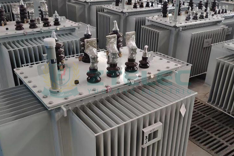
Maintenance Requirements for 500–2000 kVA Oil Filled Transformers
Regular maintenance helps detect insulation deterioration, overheating, oil contamination, leakage, and mechanical problems before they develop into major failures.
Insulating Oil Testing
Oil condition should be monitored according to transformer manufacturer recommendations and applicable maintenance standards. Common tests may include dielectric breakdown voltage, moisture content, acidity, interfacial tension, and dissolved gas analysis.
Dissolved Gas Analysis
DGA can help identify developing conditions such as overheating, arcing, or partial discharge by analyzing gases dissolved in the transformer oil. The test frequency should be based on transformer criticality, age, operating conditions, and maintenance strategy.
Leak Inspection
Tank welds, valves, gaskets, radiators, bushings, and other oil-containing components should be inspected for signs of leakage.
Cooling System Inspection
Radiators, fans, pumps, temperature indicators, and control circuits should be inspected according to the transformer's cooling configuration.
Electrical Testing
Periodic electrical inspections may include insulation resistance, winding resistance, turns ratio, grounding, and other condition-assessment tests as required by the maintenance program.
Load Management
Persistent overloading can accelerate insulation aging and increase transformer operating temperature. Monitoring load levels and balancing phases where appropriate can improve reliability.
Common Oil Filled Transformer Problems and Solutions
| Problem | Possible Causes | Recommended Action |
|---|---|---|
| Overheating | Overloading, insufficient cooling, high ambient temperature | Check load, cooling equipment, oil condition, and ventilation. |
| Oil Leakage | Damaged gaskets, valves, seals, welds or bushings | Locate the leakage source and repair affected components. |
| Insulation Deterioration | Moisture, overheating, oxidation or contamination | Perform oil and insulation condition testing and investigate the root cause. |
| High No-Load Losses | Core design, material quality or excessive magnetic flux density | Evaluate core condition and verify design and manufacturing parameters. |
| High Load Losses | Winding resistance, poor connections or excessive loading | Check winding condition, connections, load level and operating temperature. |
| Bushing Problems | Contamination, aging, moisture or mechanical damage | Inspect, clean, test or replace defective bushings. |
| Abnormal Noise | Core vibration, loose components or magnetic effects | Inspect core clamping, mechanical components and operating conditions. |
1500 kVA Oil Filled Transformer Application Example
A 1500 kVA oil filled transformer can be suitable for industrial facilities where medium-voltage utility power must be converted to a low-voltage distribution system for manufacturing equipment, motors, HVAC systems, lighting, and auxiliary loads.
Typical Configuration
A project may specify a 1500 kVA, 11 kV/0.4 kV oil filled transformer with copper or aluminum windings, ONAN cooling, appropriate tap adjustment, temperature monitoring, pressure protection, and a suitable enclosure.
The final configuration should be determined by the load profile, utility requirements, installation environment, short-circuit level, protection coordination, and applicable standards.
Expected Benefits
When properly sized and maintained, a 1500 kVA transformer can provide stable medium-voltage power distribution while maintaining reasonable equipment cost, thermal performance, and lifecycle efficiency.
Oil Filled Transformer vs. Dry Type Transformer
| Feature | Oil Filled Transformer | Dry Type Transformer |
|---|---|---|
| Insulation/Cooling Medium | Insulating liquid | Air and solid insulation |
| Heat Dissipation | Very effective | Effective but generally lower thermal transfer capability |
| Typical Installation | Outdoor substations and suitable dedicated facilities | Indoor and outdoor applications depending on design |
| Fire Considerations | Requires consideration of insulating liquid fire characteristics and containment | Generally lower fire risk with suitable dry insulation systems |
| Maintenance | Requires monitoring of insulating liquid and associated components | Generally lower routine maintenance |
| Environmental Considerations | Requires management of insulating liquid | No conventional transformer oil |
| Common Applications | Utility, industrial, renewable energy and outdoor substations | Buildings, hospitals, data centers and indoor substations |
| Lifecycle Considerations | Strong thermal performance and long service life when properly maintained | Low-maintenance operation and flexible indoor installation |
Neither technology is universally better. The appropriate choice depends on installation location, fire-safety requirements, load characteristics, environmental conditions, available space, project regulations, lifecycle cost, and maintenance strategy.
Future Trends in Oil Filled Transformer Technology
Smart Transformer Monitoring
Digital sensors can monitor transformer temperature, load, oil condition, and other operating parameters. Connected monitoring systems can provide operators with real-time information and support condition-based maintenance.
Eco-Friendly Transformer Fluids
Natural ester and synthetic ester insulating liquids are gaining attention in applications where higher fire safety and improved environmental characteristics are important.
Low-Loss Transformer Designs
Manufacturers continue to improve core materials, magnetic circuit design, winding geometry, and manufacturing processes to reduce no-load and load losses.
Amorphous Core Technology
Amorphous metal core transformers can significantly reduce no-load losses in suitable applications. They may be particularly attractive for transformers that remain energized for long operating periods.
Digital Twins and Predictive Maintenance
Digital models combined with real-time operating data can help asset managers analyze transformer condition, simulate operating scenarios, and develop predictive maintenance strategies.
Compact Substation Integration
Oil filled transformers are increasingly being integrated into compact substations and prefabricated power distribution systems. Factory-assembled solutions can simplify transportation, installation, and project deployment.
How to Buy a 500–2000 kVA Oil Filled Transformer
When purchasing an oil filled transformer, buyers should provide the manufacturer with a complete technical specification rather than requesting a quotation based only on kVA rating.
Important purchasing information includes rated capacity, primary voltage, secondary voltage, frequency, vector group, impedance, tap range, winding material, cooling method, insulation level, installation environment, transformer losses, enclosure requirements, accessories, applicable standards, testing requirements, and delivery location.
Buyers should also evaluate the manufacturer's production capability, quality control system, factory testing facilities, previous export experience, certification, warranty terms, spare parts availability, and after-sales technical support.
500–2000 kVA Oil Filled Transformer Cost Factors
The price of an oil filled transformer is influenced by more than its rated kVA. Major cost factors include copper or aluminum prices, electrical steel grade, transformer losses, voltage class, insulation level, impedance, oil type, tank design, cooling system, accessories, testing requirements, certification, packaging, and shipping destination.
For example, a 1000 kVA oil filled transformer price can vary significantly between a standard distribution configuration and a customized transformer with low-loss requirements, special voltage ratios, advanced monitoring, or additional factory testing.
For this reason, buyers should compare both initial purchase price and total cost of ownership. Lower no-load and load losses can produce meaningful energy savings over a transformer’s operating life.
Frequently Asked Questions About 500–2000 kVA Oil Filled Transformers
What is the typical lifespan of a 500–2000 kVA oil filled transformer?
A properly designed, installed, operated, and maintained oil filled transformer can provide several decades of service. Actual lifespan depends on operating temperature, loading, insulation condition, oil quality, moisture, maintenance, and environmental conditions.
What is the most common cooling method for 500–2000 kVA oil filled transformers?
ONAN cooling is widely used for conventional distribution transformers because it provides reliable natural cooling without requiring auxiliary fans or oil pumps. ONAF or other cooling configurations may be selected when additional thermal capacity is required.
Is a 1000 kVA transformer suitable for an industrial plant?
A 1000 kVA oil filled transformer can be suitable for many industrial facilities, but the correct rating must be determined from the actual maximum demand, motor starting requirements, power factor, harmonics, future expansion, and utility specifications.
What is the difference between a 1500 kVA and 2000 kVA oil filled transformer?
The main difference is rated apparent power capacity. A 2000 kVA transformer can supply a higher electrical load than a 1500 kVA unit, but the larger transformer may also have higher initial cost and different loss characteristics. The selection should be based on present and future load requirements rather than simply choosing the largest available rating.
Can oil filled transformers be installed indoors?
Oil filled transformers can be installed in certain indoor applications when the transformer design, insulating liquid, fire protection, oil containment, ventilation, clearances, and local regulations permit it. However, dry type transformers are often preferred where indoor fire-safety requirements are particularly stringent.
How often should transformer oil be tested?
Oil testing frequency depends on transformer criticality, operating conditions, age, loading, manufacturer recommendations, and the applicable maintenance program. Oil condition testing and DGA can be scheduled periodically or used as part of a condition-based maintenance strategy.
What standards apply to oil filled transformers?
Applicable standards depend on the market and project. Common international standards include the IEC 60076 series and IEEE C57 standards, while national standards may also apply. The manufacturer and buyer should confirm the required standards before engineering and production begin.
The 500–2000 kVA oil filled transformer series provides a flexible solution for industrial power distribution, commercial facilities, utility substations, renewable energy projects, mining operations, and infrastructure applications.
From 500 kVA and 750 kVA units to 1000 kVA, 1250 kVA, 1500 kVA, 1600 kVA, and 2000 kVA oil filled transformers, each capacity serves a different range of electrical loads and project requirements.
When selecting an oil filled transformer, engineers and procurement teams should evaluate rated capacity, voltage ratio, load characteristics, transformer losses, cooling method, insulation system, installation environment, protection equipment, applicable standards, maintenance requirements, and total lifecycle cost.
As power demand continues to increase in industrial facilities, renewable energy projects, data centers, infrastructure systems, and utility networks, modern oil immersed transformer technology is also evolving through low-loss core materials, eco-friendly insulating liquids, smart monitoring, predictive maintenance, and digital asset management.
For buyers looking for a reliable 500–2000 kVA oil filled transformer manufacturer, the most important consideration is not simply the lowest purchase price. Manufacturing capability, engineering experience, material quality, factory testing, certification, delivery performance, warranty support, and long-term technical service should all be evaluated before placing an order.
Cast resin transformer
dry type transformer
Indoor Transformer
cast resin dry type transformer
750 KVA oil filled transformer
- more+releated article
- 2026-08-10Oil Filled Transformer Series Overview: 500–
- 2026-07-31Cast Resin Dry Type Transformer: Fire-Safe Ind
- 2026-07-30750 KVA Oil Filled Transformer Manufacturer |
- 2026-07-2911kV Dry Type Transformer – Ultimate Specifi
- 2026-07-287.2KV Switchgear: Complete Guide to Technical
- 2026-07-27Prefabricated Substation Price Guide 2026: 200
- 2026-07-25Oil Immersed Transformers Explained: Cooling S
- 2026-07-24Gas Insulated Switchgear (GIS) vs Air Insulate
- 2026-07-23315 KVA Cast Resin Dry Type Transformer – Co
- 2026-07-2233KV GIS Switchgear Installation & Mainten
- ELECTRICAL INSULATION BOARD MATERIALS
- ELECTRICAL INSULATION MATERIALS
- POWER TRANSFORMER
- ENAMELED WIRE
- SWITCHGEAR



cast resin dry type transformer
dry type transformer
Indoor Transformer
Cast resin transformer
750 kVA transformer
750 KVA oil filled transformer
750 kVA transformer manufacturer
Oil immersed transformer
Dry Type Transformer China
11kV Transformer Manufacturer
11kV dry type transformer
11kV cast resin transformer
7.2kV Medium Voltage Switchgear
7.2KV Metal Clad Switchgear
7.2KV Switchgear
prefabricated substation price
package substation price
prefabricated substation cost
compact substation price
ONAF transformer
il immersed transformer
transformer cooling
oil filled transformer
ONAN transformer
Air Insulated Switchgear